Ah, good old shader graphs. The noodle-based user interfaces that graphics engineers tend to hate, and artists tend to begrudgingly like. The premise of shader graphs is that the artist can connect some nodes to visually program the appearance of materials, and they can do so even if they aren’t comfortable writing code. This is a substantial value proposition, so I think shader graphs are an important feature to have in an artist-facing tool. Shader graphs also make it easier (compared to raw HLSL) to calculate analytical derivatives of texture coordinates, which is an important feature to have when doing Visibility Buffer rendering.
Shader graphs are also often misunderstood, with many users wanting full flexibility. However, a lot of the power of a shader graph comes from its constraints. All shader graphs have an implicit contract that dictates quite a lot about the rest of the rendering pipeline. We’ll have a look at this contract and its impact in this blog post.
Quick terminology refresher
A shader graph is a directed acyclic graph. This means that
- The edges of the graph have a direction. E.g. the UV node is fed into a texture sampling node, but not vice versa.
- There are no cycles. E.g. you cannot plug the output of a node back into itself.
In graph theory, nodes which have no incoming connections are called source nodes, and nodes which have no outgoing connections are called sink nodes. In shader graph terminology, sink nodes are sometimes called master nodes.
Sources nodes
Source nodes in shader graphs are usually values like the normal, position or UV of the shaded fragment. These just automagically “appear”, i.e. the code generator ensures that they exist.
Sink nodes
Sink nodes in shader graphs are a bit more interesting than source nodes, and depend on the shader graph in question. This is a non-exhaustive categorization of sink nodes:
- Unlit
- Lit
- Layered & mixed lit
1. Unlit
This kind of sink node directly has a color slot. You do whatever calculations you want, feed in a color, and that’s the color that will be displayed. Unity’s unlit master node is an example of this kind of a sink.
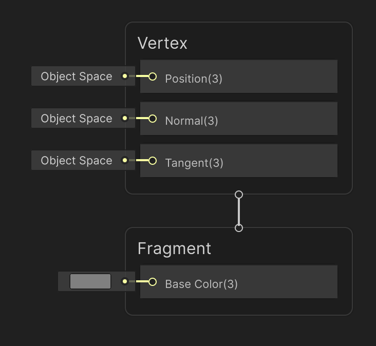 Unity’s unlit sink node. We’re ignoring the “Vertex” section in this blog post. Pay attention to the “Fragment” section.
The nice thing about this kind of sink is that you have a high degree of control. You don’t have to stick to Physically Based Rendering. You can shade as your heart desires.
There’s several downsides though:
- You can’t properly capture the concept of a light loop in shader graphs. It’s a bit clunky to do “foreach light” in an acyclic graph.
- Not all lights are created equal. Shading punctual vs area vs environmental lights involves different math. The user would be responsible for handling this math correctly, which would also likely be clunky.
- Unlit graphs don’t extend naturally to deferred rendering. Given arbitrary computation, how do we figure out which GBuffers to lay down, and how to encode them? How do we write a deferred lit pass, if we cannot guarantee certain homogeneity of materials?
2. Lit
This kind of sink node takes an opinionated surface description as input. For instance, by accepting metallic, smoothness, emission values, it’s mandating a PBR material with a metallic workflow, as opposed to a specular workflow.
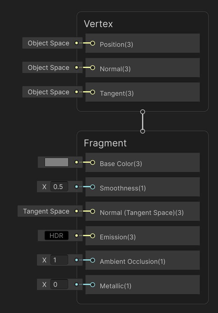 Unity’s lit sink node
Now we’ve given up some artistic control. You can’t create a fully custom toon-shaded effect with this construct. With these restrictions come some benefits:
- The artist doesn’t have to worry about light loops. They provide a surface description, and the renderer takes care of looping over lights.
- The artist doesn’t have to worry about the differences in math across light types. The renderer is responsible for calculating the correct exit radiance, given a surface description.
- GBuffer laydown is straightforward. The renderer knows what the surface description looks like. It finds a way to fit it into GBuffers. Since the GBuffer format is known, the deferred lighting pass also becomes doable.
If we think of the shader graph as the artist-programmable part of the pipeline, we can see in the diagram below that all of the artist-programmability occurs before the GBuffer is laid down.
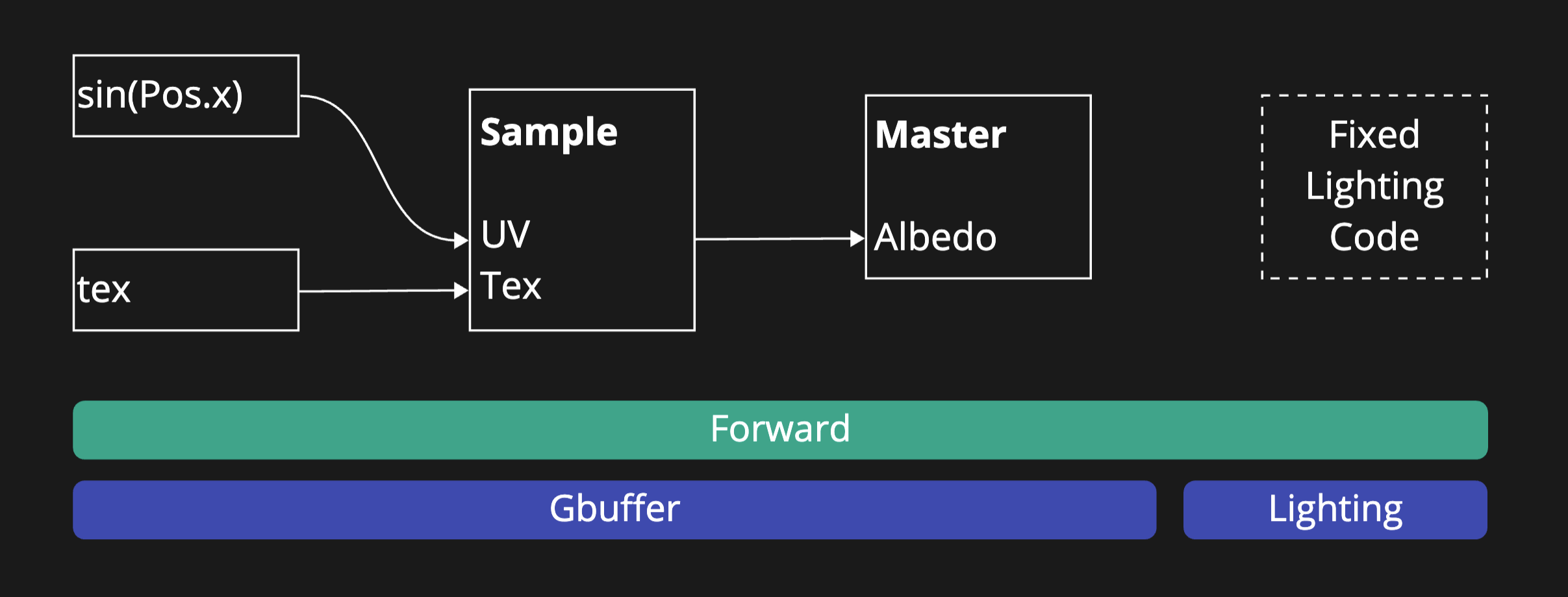 Figure 1
3. Layered & mixed lit
This kind of sink refers to a material that is a combination of materials layered and mixed together.
Layering is vertical stacking of materials on top of each other, e.g. semi-transparent laminate on top of wood. In this case, there are two interfaces that scatter light: air-laminate and laminate-wood.
Mixing is a more horizontal operation. Imagine that within a fragment, you want to shade a surface that is 50% metal and 50% rust. To do this more accurately than slapping on a value of 0.5 metallic, you should do the math twice–once for metal and once for rust–and then take an average of the two reflectances.
Now, you might want to layer and mix any number of these things in any order. E.g. imagine wood layered with laminate above it, and all of this layered with a horizontal mix of sand and air. The possibilities are endless. This arbitrary layering is exactly what projects like MaterialX try to serialize and standardize.
This expressivity comes with big downsides, especially when it comes to real-time rendering. Let’s look at this graph:
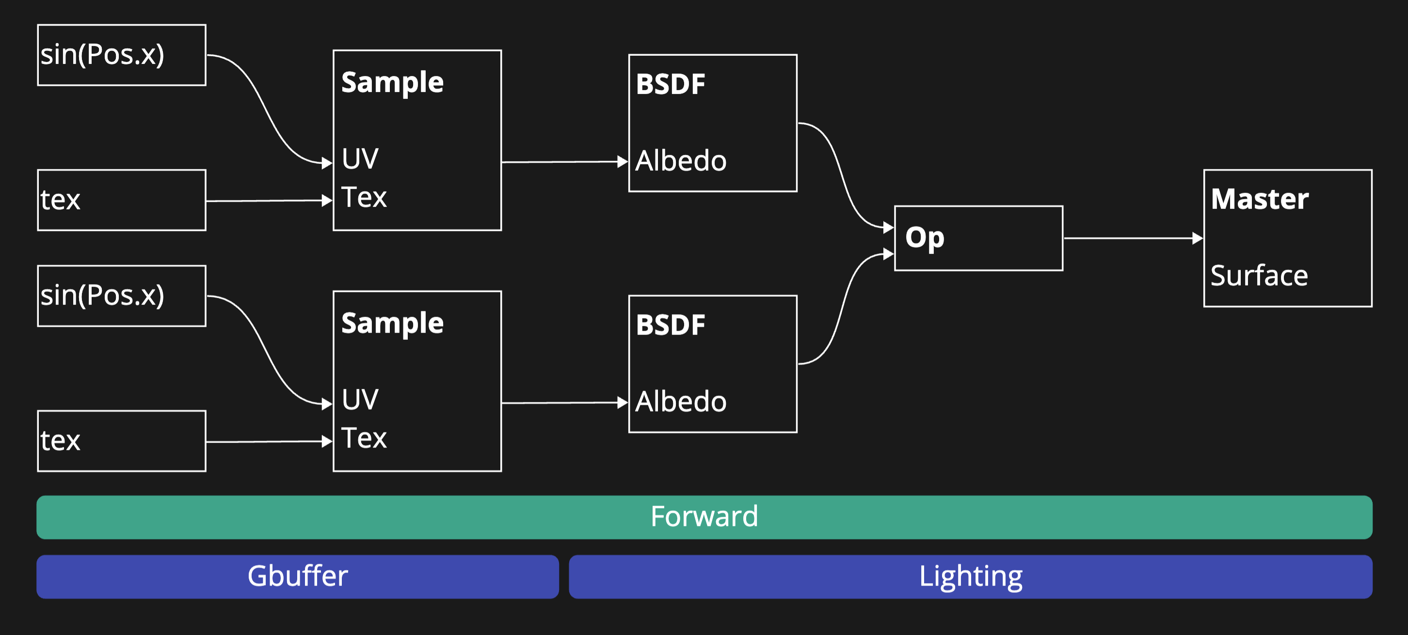
In the graph above, we’re calculating two BSDFs and then combining them with an operator like mixing or layering. In Figure 1, the artist-programmability occurred only in the GBuffer laydown. In contrast, now we have to do GBuffer laydown for the two BSDFs, but we have to apply the artist-programmed operator in the deferred lighting pass. The mixing operator is a simple weighted sum, but the layering operator needs information about how much transmittance the top layer has. All this information needs to be passed to the deferred lighting pass.
To lay out our challenges:
- The GBuffer format and thickness depends on the number of BSDFs being evaluated. The more complex the surface, the more GBuffers are needed. If you don’t limit the complexity and the number of layers, you will run out of textures and/or UAVs to write to.
- Even if you limit the number of BSDFS, the relationship between the BSDFs needs to be encoded. E.g. one material might be
mix_op(layer_op(bsdf_0, bsdf_1), bsdf_2, 0.5), while another material might belayer_op(bsdf_0, layer_op(bsdf_1, bsdf_2)). So you still need to encode these operators in the GBuffers. This encoding takes up so much space, that you run out of textures again, or you pay dearly in texture bandwidth.
Side-note: Unreal’s Substrate
Unreal’s Substrate Unreal Engine Substrate: Authoring Materials That Matter [PDF] by Sebastien Hillaire and Charles de Rousiers. works around these challenges pragmatically.
It bundles together certain BSDFs into concepts it calls Slabs. So a certain slab will have a diffuse BSDF (in case of a dielectric material), a specular BSDF, and optionally fuzz, subsurface, etc. The order of these within the slab is predefined. You cannot put fuzz underneath your specular for example.
Secondly, Substrate does tree flattening. This means that during GBuffer laydown, it will walk the BSDF tree, calculate down transmittance and coverage, and then encode these into the GBuffer. Then the BSDF tree can be discarded. During deferred lighting, the transmittance and coverage are enough.
This ameliorates the two aforementioned challenges:
- The number of slabs are limited, and there’s a fixed structure within a slab. This limits the possibility space, allowing for a feasible GBuffer.
- The ingenious tree flattening allows the tree structure to be discarded after GBuffer laydown. Lighting is reduced down to something akin to a weighted sum.
Conclusion
This was a bit of a brain dump, but I guess the broad points I want to make are:
For users of shader graphs: When I talk to technical artists, they often want complete flexibility. They often ask “why can’t I write a toon shader in a shader graph?”, or “Why can’t you allow complete control of the light loop in a shader graph”? The answer is performance and cross-platform scalability. Often you need deferred rendering. Sometimes, you want to disable a feature on a specific platform without changing the shader graph, in order to reduce VGPR pressure. Mind you, there are creative possibilities in this space, but the answer isn’t a single clear path forward. And engines will often (correctly) prioritize scalability over expressivity in this tradeoff. I believe it is important to allow for a customizable light loop, but I think the answer lies in readable HLSL APIs and user-definable sink nodes rather than out-of-the-box shader graph support for arbitrary lighting.
For designers of shader graphs: When designing a shader graph, be clear about your user contract. You might accidentally make a node that works in forward, but not in deferred, or in Visibility Buffer rendering. I didn’t even touch upon tessellation or vertex displacement. These cause additional design wrinkles and at simultaneously open up new possibilities.
Shader graphs are a rich design space, so go forth and explore!